Wankel defined the operation of the engine designed by him, as: ” The automobile engineering basics rotary internal combustion engine in which a triangular rotor rotates inside a specially designed housing, and performs the same functions as the pistons of a conventional engine, but reducing weight and number of moving parts. ” Following with a previous post, I will explain in more detail the elements of the engine of this marvel of engineering.
The rotary engine is an internal combustion engine with a concept of operation very different from what we are used to. Like the alternative engines, the rotary engine also develops the same 4 times and uses the pressure on the fuel and the air.The rotary engine also uses combustion, but in a single engine block in the form of 8, unlike the cylinders of conventional engines. This engine block has a triangular rotor that divides the block into 3 cavities, which expand or contract as they rotate.
Rotary motor, the rotor

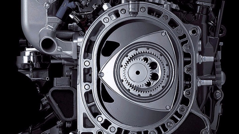
The automobile engineering basics rotor fulfills the same function as the piston-connecting rod assembly in the reciprocating engine, transmitting the pressure exerted by the combustion gases directly on the crankshaft. At the same time, the rotor does the work of the intake and exhaust valves in an alternative engine. In each of the vertices of the rotor are placed sealing elements, as well as along both side faces, to prevent the air-fuel mixture, burnt gases or lubricating oil from leaving the space in which they are confined. The gear and the rotor bearing are located inside it. The contour of the rotor has the shape of the inner envelope of the stator.
The small free space that exists between the rotor and the stator is achieved by machining the rotor according to an epitrochoid somewhat smaller than the one that actually forms the stator. In the face of the engine performance, it is important that this space or game be as small as possible. However, thermal deformations and manufacturing tolerances must be taken into account, among other aspects. In the end, this distance is usually around 0.5 mm.
Rotary motor, the stator

The stator of the automobile engineering basics rotary engine is the equivalent to the set formed by the engine block and the cylinder head of the reciprocating engines. For a single rotor motor, the stator consists of three parts: one, peripheral, that surrounds the rotor; and two others, lateral, one on each side of the rotor. In the rotary engine, the combustion chamber moves following each of the phases of the four-cycle cycle. The zone where the mixture is admitted is cooled with the entrance of the mixture, while the expansion zone is exposed to high temperatures. Something similar happens with pressures. The pressure exerted by the segments (due to the centrifugal force) and the burnt gases, wear out the inner surface of the peripheral stator in very localized areas (related to the points where combustion takes place).
The stator can be subjected to a significant gradient of pressures and temperatures (jumps of 100 ° C are easily obtained). Therefore, the basic characteristics that the material of the peripheral stator must fulfill are: to provide sufficient resistance to resist the stress caused by combustion; ensure the minimum temperature difference and resist the thermal stresses caused by this gradient, as well as ensure good cooling and lubrication conditions; and resist with the least possible deformation to ensure good sealing of the combustion chambers.
Transmission gears of the rotary engine of a car
This mechanism is formed by a pinion (gear of external teeth), fixed to the lateral cover of the stator, and another, of internal teeth, solidly attached to the interior of the rotor. The first one remains immobile (it acts as the base circle of the curve) and the other, when engaging with it, perform the generation movement of the epitrochoid, as already described above. The ratio between the number of teeth of both gears is 2: 3.
This difference provides a 1: 3 transmission ratio between the rotor speed and the output shaft speed. The fixed gear is fitted to the side cover of the stator and fastened by fixing screws. In addition, it is given a suitable shape and thickness so that the gear has acceptable stiffness and fatigue resistance. As for the internal tooth gear, it has a cylindrical shape of a very small thickness and is housed inside the rotor. Like the fixed gear, it can be fixed by screws, although it is more common to use small springs that, while holding the gear, absorb part of the loads to which it is subjected.
Sealing mechanism of the rotary engine of a car

The mechanism that ensures the tightness of the combustion chambers in the rotary engine is equivalent to the flexible rings that are attached to the pistons in the reciprocating engine. In this case, it consists of sealing elements arranged in three characteristic ways, designed to ensure that gases and fluids remain in place at all times. The segments of the rotary motor are subjected to very high pressures, as well as to quite high working temperatures. Therefore, a correct study of its design is very important to define both the form and the material. Like the material, the surface treatment of the piece with which the segments are going to maintain contact requires a special consideration: peripheral and lateral stator.
Today, rotary automobile engineering basics engines can not unseat alternative engines but in the future could play an important role becoming engines of transition to new engines more efficient and respectful of the environment or new energy transformation processes. Do you think that one day they will apply to all cars?


+ There are no comments
Add yours